Nowhere do foundry know-how and new design thinking meet more acutely than when designing the sand mold for the 3D printer. Here at CASTFAST, we work closely with our casting foundries to ensure that the mold is perfect the first time – no matter where it is printed – and that the casting runs exactly as the casters imagined.
On the one hand, the mold should behave and be able to be handled in exactly the same way as if it had been produced by hand, but on the other hand, differences in the details of mold production must be taken into account for printing and transport.
To this end, we provide foundries with guidelines and rules – both general and casting-specific. Here we briefly show what foundries can expect. In newspaper printing, this means pre-press – everything that has to happen before the actual printing. This is what the pre-press stage at CASTFAST looks like:
The CASTFAST team provides the 3D model of the casting for the design of the sand mold, as well as a document with general key data on the mold – such as maximum size, tolerances, labeling, attachment of transport holes – and design tips. The foundry then adds the casting technology to the 3D model of the casting as a positive model: Gating system, filters, risers, cooling irons and core marks are also applied by the foundry.
For dimensions for filters, feeders and heat sinks, we provide a tolerance of 1 mm to be added. Bevels of the casting are included in the 3D data and, thanks to the 3D sand printing process have no influence on the sand mold design.
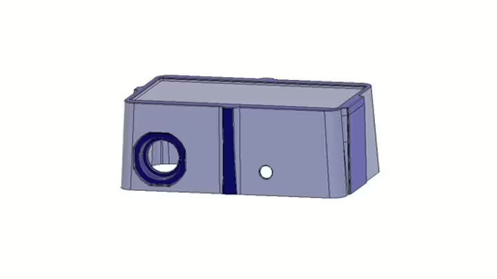 The 3D drawing also already contains the machining allowances (we mark these in blue). We provide foundries with the maximum dimensions and the minimum wall thickness of the mold in our design guidelines. This results in the “sand cuboid”, from which the 3D model of the raw part is subtracted together with the casting technique to obtain the 3D drawing of the final mold. Almost like a traditional pattern. Only virtual.
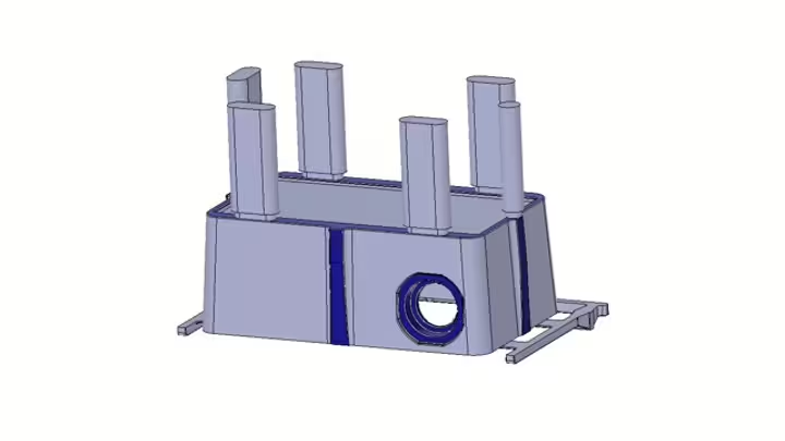
For the positive 3D model, the casting should sit directly on the gate; cooling irons are also placed directly on the casting. Positive placeholders for the risers, on the other hand, should be placed flush on the casting.
When designing the “virtual” feeder, it is important to note that a slightly larger placeholder of the feeder is used for the sand mold construction so that the real feeder can be easily inserted by hand later. The placeholder only has the actual dimensions of the riser in the lower area so that it fits snugly here. This can be easily achieved by taking the 3D file of the riser and extending the upper half upwards.
We require the print file in .step format in accordance with ISO 214. All objects (casting technology, cores, molded parts) must be provided in one file. To ensure a high degree of automation in order processing, we also request standardized file names (more on this in our order documents).
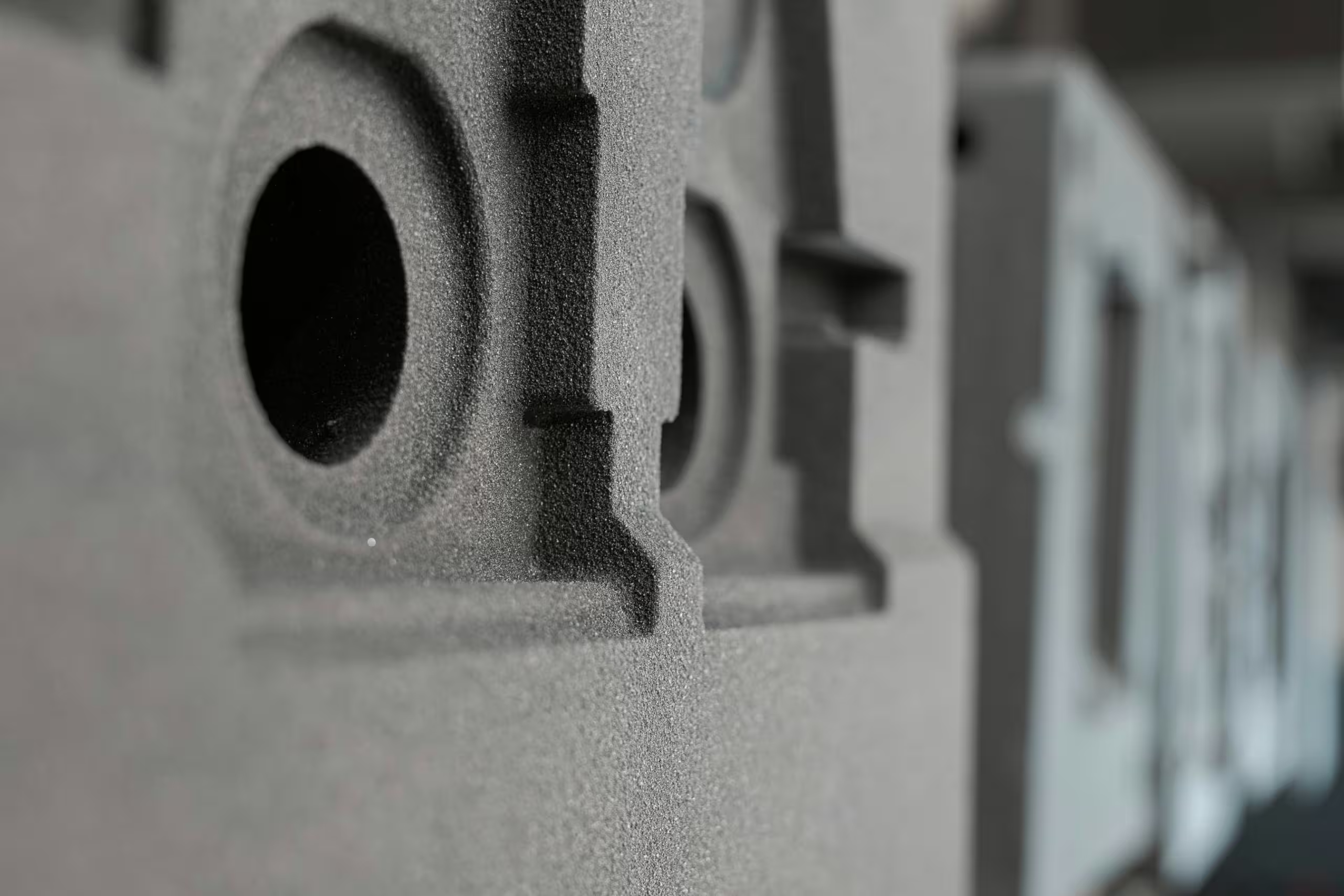
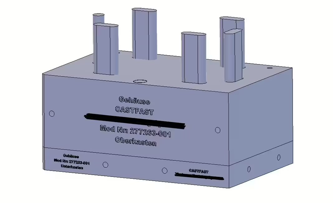
As a rule, transportation and guide holes should have a diameter of 31 mm in compliance with the specified minimum wall thickness. The 31 mm is an empirical value – many of our customer and supplier foundries use rods with a diameter of 24-30 mm, which is why 31 mm always fits. Foundries can adapt this to their own requirements.
Finally, all form segments must be labeled with text according to the scheme provided in the order documents.
And this is the CASTFAST-style pre-press stage. This means that the file can go directly to the printer (don’t worry, we check it beforehand), the sand mold can be printed and delivered to the foundry for casting. And if the casters can only get the casting technique on paper from the 2D drawing, we are also happy to create the print file.
Fancy faster or more complex sand molds? Simply order here. We print, casters cast.