You can find information on tolerances, surfaces, machining allowances and the design of radii and lift-out chamfers on the component in our design guidelines
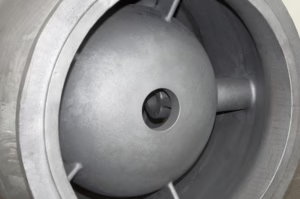
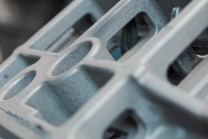
Printed casting is our sand casting process for fast production. We achieve surface roughnesses of Ra 50 to 100 for all materials.
| GTB15 | GTB16 | GTB17 | GTB18 | GTB19 | GTB20 |
|---|---|---|---|---|---|
| DCTG8 | DCTG8 | DCTG9 | DCTG10 | DCT12 | DCTG13 |
Status: 28.01.2025
Use the largest possible radius (marked as 1st choice)
Use next smaller alternative if 1st choice leads to feasibility problems.
| Longest axis on the component | Outer radii | Inner radii |
|---|---|---|
| < 200 mm | 3 mm | 1st choice: 8 mm |
| Alternative: 5 mm | ||
| > 200 mm | 1st choice: 5 mm | 1st choice: 15 mm |
| 1st alternative: 10 mm | ||
| Alternative: 4 mm | 2nd alternative: 8 mm |
Please color measurement areas BLUE.
|
|
The allowance on the casting after casting may be lower due to shrinkage within 1/4 of the DCTG level.
* The longest axis on the component specifies the allowance for all machining surfaces.
** from DIN EN ISO 8062-3:2008-09 point 8.1: In sand casting, top surfaces may require larger machining allowances (additional machining allowance) . The additional machining allowance is based on ISO 1685-1. We will inform you about the additional machining allowance after the order has been placed and the casting position has been successfully determined.
Status: 28.01.2025
Use the largest possible radius (marked as 1st choice)
Use next smaller alternative if 1st choice leads to feasibility problems.
| Longest axis on the component | Outer radii | Inner radii |
|---|---|---|
| < 200 mm | 1 mm | 1st choice: 3 mm |
| Alternative: 2 mm | ||
| > 200 mm | 1st choice: 3 mm | 1st choice: 5 mm |
| 1st alternative: 4 mm | ||
| Alternative: 2 mm | 2nd alternative: 3 mm |
Please color measurement areas BLUE.
|
|
The allowance on the casting after casting may be lower due to shrinkage within 1/4 of the DCTG level.
* The longest axis on the component specifies the allowance for all machining surfaces.
** from DIN EN ISO 8062-3:2008-09 point 8.1: In sand casting, top surfaces may require larger machining allowances (additional machining allowance) . The additional machining allowance is based on ISO 1685-1. We will inform you about the additional machining allowance after the order has been placed and the casting position has been successfully determined.
Status: 28.01.2025
Use the largest possible radius (marked as 1st choice)
Use next smaller alternative if 1st choice leads to feasibility problems.
| Longest axis on the component | Outer radii | Inner radii |
|---|---|---|
| < 200 mm | 3 mm | 1st choice: 8 mm |
| Alternative: 5 mm | ||
| > 200 mm | 1st choice: 5 mm | 1st choice: 15 mm |
| 1st alternative: 10 mm | ||
| Alternative: 4 mm | 2nd alternative: 8 mm |
Please color measurement areas BLUE.
|
|
The allowance on the casting after casting may be lower due to shrinkage within 1/4 of the DCTG level.
* The longest axis on the component specifies the allowance for all machining surfaces.
** from DIN EN ISO 8062-3:2008-09 point 8.1: In sand casting, top surfaces may require larger machining allowances (additional machining allowance) . The additional machining allowance is based on ISO 1685-1. We will inform you about the additional machining allowance after the order has been placed and the casting position has been successfully determined.